Decision Tree Node Properties
The Decision Tree can be modified so that each click on a node results in some predetermined event. The event that results from clicking a node is determined by properties attached to the node. Properties are attached to a tree node using the Set Item Property window, which is accessed by first highlighting the node and then clicking on the Property Button at the bottom of the Development mode screen.

Different types of properties cause different events to occur when a tree node is double clicked. The following categories of properties can be set for a tree node.
Types of Properties
Pop Up New Window: Selected when a new window should open. For example, this option is typically selected for each Decision Tree option created.
Action: An action initiates the execution of an internal program (i.e. Decision Tree or Chief Complaints screen) or external application.
View: Adding a view opens a window that displays information. For example an instruction document used to review information with a patient.
Key: A key is a special purpose property used to pass parameters, such as to SQL queries. Feature is used often for QA’s.
SQL Alert Query: The alert property is used to generate a message based on the results of the SQL query. For example, Patient Needs Mammogram.” The ‘No Alert’ Text field is used to enter a specific message that is displayed when the query generates no results. The ‘Alert’ Text field is used to enter a specific message to be displayed when query results are generated.
Billing: Billing properties are used when a Charge should be automatically sent to the accounts receivable system. For example, a Flu Vaccine branch generates a charge for the procedure when it is selected.
Order: An order property is used when an Order should be automatically sent to the Order entry system. For example, a “Two Week Follow Up Appointment” branch generates an order to the scheduling department to schedule that follow-up.
RX: The RX property is used to allow a drug to be added to the patient’s medications. For example, a branch called Amoxicillin can be selected, which generates the prescription in the Medications screen.
Boilerplates: This section of the screen allows “new” boilerplates to be created and existing boilerplates to be edited or deleted. Boilerplates may also be activated by selecting an item from the Select Boilerplates list and clicking on the left arrow key, which moves it to the Boilerplates Used field. To remove an item in the Used Boilerplate field, select the item and click on the right arrow key to return it to the Select Boilerplates list.
Sequence of Events
When a tree node is double-clicked, the properties attached to the node will always activate events in the same order. This order of priority is as follows:
1. View Property with “!” Prefix
2. Action
3. Order
4. Billing
5. RX
6. View Property (All Other)
7. Alerts
Action Properties
Action properties can initiate events when a node is clicked. A list of the valid action property values can be found here.
Scripting Action Properties
Under normal circumstances, only one action property may be attached to a tree node. This can be overridden, however, by a special action property called #SCRIPT. This action property can call up a file that contains definitions of common scripts and is thus able to serve as a macro. One click can initiate several action properties in sequence.
Syntax of Action Property
#SCRIPT:ScriptName
Where ScriptName is a section defined in SCRIPT.TBL and should be stored in the OUTLINE directory.
Contents of SCRIPT.TBL
[ScriptName]
1=#QA:EXAM.QA
2=#QA:ROS.QA
3=#FAMILYH
4=#MEDS
5=#ALLERGY
[AnotherScript]
1=#CHIEF
2=#RX
[Colposcopy]
1=#QA:PRCOLPO.QA
2=[69]#EDITC:PRCOLPO.TXT
When defining action properties in a SCRIPT.TBL file some rules apply:
- It must include only Action Properties (View Properties, SQL Alert Properties or boilerplate properties are not allowed).
- The action properties must be labeled numerically in consecutive order and must begin with 1. It will end on reaching the last number listed with an action or on the first number reached without an entry.
- Some action properties are modal (interrupting all other processes until the modal window is released) and some are modeless (opening up a window in the background while continuing with other tasks). The implications of these relate to the sequence of items. Modeless action properties (such as #ICD9) will return immediately and proceed to the next action property. This may not be an expected event so test the sequence of events because scripts are often used to force users to fill in a series of data entry screens and an unintended result may occur.
 When
a script is active, a special End Script button appears on the lower right
corner of the application window, which is shown here. It allows the user
to terminate the script after it has been initiated. For example, if the
user realizes he is in the wrong patient chart, he can click on End Script
rather than running through the list of screens included in the script.
When
a script is active, a special End Script button appears on the lower right
corner of the application window, which is shown here. It allows the user
to terminate the script after it has been initiated. For example, if the
user realizes he is in the wrong patient chart, he can click on End Script
rather than running through the list of screens included in the script.
View Property
A View Property is used to display a message to the user. This can be shown as a full screen with scrollable text or as a small message box. The text shown in a View property can come from a parameter passed to the view property or it could be a text file found in the OUTLINE directory. You can embed SQL statements in these text files, which will be discussed in greater detail under the Document Interpreter section.
If the View property is a file name, the file should be located in the TABLES directory and must be a TXT file (containing ANSI text only). An example of such a document is displayed here. Note that a print button is provided to allow printing of the contents of this view.
A View Property should be entered in the following format: VWSIDE.TXT.
View Property as a Message Box
The View Property can be used as a Message Box. Instead of placing a file name as the property, you may type in the actual message but must precede it with the “!” exclamation mark symbol.
View Property Print with Header
An option to turn the header on/off when printing from #EDITC or a View Property window is available in DIMPROF?.INI:
[DIM]
Print Header in View Property=1 (1=On/0=Off)
Key Property
A Key Property is used to allow a value to be kept in a tree node. This value can be retrieved using the global variable &KEY which can be used in SQL Queries or passed as a parameter to some special function such as SQL Questionnaires (discussed later). This allows queries to be done in the context of the tree node that has been clicked. This is an advanced feature.
SQL Alert Query
SQL Alert Queries are used to display alert messages when a particular tree node is clicked. A query must be provided and the result of the query will determine which of two separate messages (optionally provided) will be displayed.
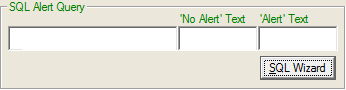
SQL Alert Query field, if preceded by a “?” is expected to be the name of a query created using the SQL Wizard. If this is not preceded by a “?”, it is assumed that you have provided the file name of a file containing a SQL script which by convention should have the name *.SQL. The SQL file must be located in the OUTLINE directory.
The ‘No Alert’ Text is a text file, which is displayed if the SQL query returns no results.
The ‘Alert’ Text specifies the name of a text file that is displayed if the SQL Query returns a result
The SQL Wizard reduces the steps required in creating an alert property. Clicking on the button displays the window below.
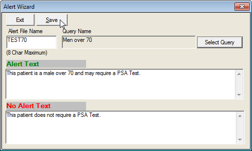
The sample alert above is filled in with data. The Query Name "Men Over 70" was created using the Select Query button which displays the window below:

You may define any query of your choice by clicking on the Add button. This will display the Query Properties window below, which displays the “Men Over 70” query already defined

The SQL Query Wizard can be used to perform complex queries via the selection of values as shown in the example above, as well as customized SQL queries.
Billing Property
A Tree node with a Billing Property will cause charges to be automatically entered in the billing system (subject to an optional confirmation). Charges entered in the Decision tree must have information that matches the Fee Schedule based on the patient’s Fee Schedule code and the selected procedure code.
The Billing property must be entered using the following format:
Procedure Description |Diagnosis Description |CPT |ICD9 |Units |Facility | Remark
Spaces at the end of each parameter are ignored.
An unused parameter is still delimited by a “|” Pipe symbol (it must be included).
If this property is used to enter charges, then the Procedure Description and CPT code are required. All other fields can be left empty or blank.
If this Billing property is being used to create a Diagnosis entry in the problem list, you may fill in only the Diagnosis Description and ICD9 code. Use of billing property for this purpose, however is no longer recommended and is included only for backward compatibility.
Billing Macros
Instead of creating charges singly, one may also automatically trigger a series of charges with one click. This is done using the Billing Macro feature. Macros are defined in MACRO.TBL in the OUTLINE directory. A macro is nothing more than a series of order properties, which are identified by one tag name. This tag name can then be placed in the Order Property Field instead of the usual order property by preceding it with a “#” symbol. Up to 12 charge items can be used in one Macro. Below is an example.
Billing Property: #ARTHRITIS
Macro is it appears in MACRO.TBL
[ARTHRITIS]
1=Uric acid Blood Chem||84550
2=Ded rate||85651
3=Fluorescent antibody||86255
4=Rheumatic factor||86430
Billing Event
When a Tree node with a Billing Property is clicked and billing confirmation is requested, the following screen will appear.
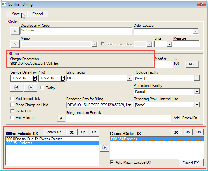
This window is the same window used for Orders confirmation when Billing and Orders properties are populated. When only the Billing property is provided, the "Orders" sections of the confirmation window are disabled.
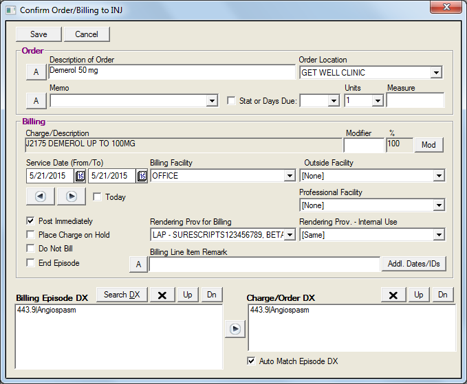
Other fields on the screen include:
ServiceDates default to today’s date, however the user is able to change using the date navigation tools.
ApplicableDiagnosis defaults to the highest ranking diagnosis as entered in the Problem List.
Facility defaults to the last facility selected.
Units typically default to “1”, but may be changed using the dropdown arrow. Users can enter up to ‘100’ in this field.
RenderingDoctor for Billing will default to the current user’s Rendering Doctor code (a Security setup) or to the last one selected.
Rendering Doctor - Internal Use is selected when the rendering provider cannot bill for himself (such as with a Physician’s Assistant, Nurse Practitioner or a Resident/Intern).
A modifier button will allow the user to pick out a valid modifier for the fee, which may be used to justify a change in pricing or to satisfy minimum documentation requirements. When the modifier button is clicked the choices will be presented in text form and, when the correct modifier code applicable to the CPT is selected, the predetermined effect on pricing (if any) will be automatically calculated. This is set up in the Modifier Table.
Orders Property
An Order Property can automatically initiate an order when a tree node is clicked. By using the additional scripting capability, a series of orders can be initiated.
Order properties are entered using the following format:
Department Code | Order Description^Order Code |Units |Measure |Memo |Stat Flag |Due
All parameters other than for the Department Code are optional.
An unused parameter is still delimited by a “|” Pipe symbol (it must be included) and spaces at the end of each parameter are ignored.
Department Code – this must be a valid code for a department and cannot exceed 5 characters. Department codes are defined in DEPT.TBL in the OUTLINE directory.
The standard departments predefined are:
Department Code |
Purpose |
CT |
CT Scan Orders |
EDU |
Patient Education Orders |
INJ |
Injection Orders |
IV |
Intravenous Orders |
LAB |
Lab Orders |
MRI |
MRI Orders |
NUCL |
Nuclear Medicine Orders |
NURSE |
Nurse Orders |
PATH |
Pathology Orders |
PHOTO |
Photographer (Fundus Photos) |
PROC |
Procedure Orders |
RAD |
Radiology Orders |
REF |
Referral Orders |
REFD |
Referral for Diagnostic Tests Order |
REFUS |
Refused Services |
SCHDP |
Scheduling of Procedures Orders |
SCHED |
Scheduler/Front Desk Orders |
STAND |
Next Visit Orders/Standing Orders |
SURG |
Surgery Orders |
TECH |
Ophthalmic Technician |
TRANS |
Transcription Orders |
ULTRA |
Ultrasound Orders |
VER |
Insurance Verification Orders |
VID |
Video – Patient Education |
Order Description – An order description can contain any text but cannot exceed 40 characters. If a longer description is required, consider placing it the memo area.
Order Code – this is an optional short identifier to the order. This is used internally only and is not exported out to other systems.
Units – units are used to specify a count to the order. Users can enter up to ‘100’
Measure – if units are specified, this defines the unit of measure used
Memo – this is used to automatically add additional text to the order, such as to provide more detail. This memo field may be to 200 characters long.
Stat Flag – this value may be a Y or blank. A “Y” value indicates that the order should be performed Stat and is marked as due immediately.
Due Days – this value specifies when the order is due and is counted as the number of days from today. Thus a due days value of 60 will give the order an Expected Completion date before 60 days from today, after which it will be labeled as past due. Due days can be manually provided or a default value can be specified in the DEPT.TBL file for each department code, which will override any parameters entered here. However, default values can be changed by the user on the Order Confirmation window.
Find Button –In order to ensure that order descriptions are consistent across multiple tree nodes and multiple tree INI files, you can use the Find Order Code button which is the end of the Order Property area. This will allow you to search for orders by department and by description. Thus you will find all occurrences of an order and will be able to identify differences in spelling.
The Order Table, which is used by the Find Order window, is automatically populated each time an order property is used. Thus, simply testing out all orders (by clicking on the tree nodes to which they belong) automatically sets up the values for the find feature.
Order Macros
Instead of creating orders singly, one may also automatically trigger a series of orders from one click. This is done using the Order Macro feature. Macros are defined in OMACRO.TBL in the OUTLINE directory. A macro is nothing more than a series of order properties, which are identified by one tag name. This tag name can then be placed in the Order Property Field instead of the usual order property by preceding it with a “#” symbol. A maximum of 16 order properties (including Order Memos) can be included in an order macro. Below is an example.
Order Property: #LAB SERIES 1
Macro is it appears in OMACRO.TBL
[Lab Series 1]
1=LAB|Serum Creatinine||||||N
2=LAB|Creatinine Clearance||||||N
3=LAB|Digoxin Level||||||N
4=LAB|Dilantin Level||||||N
5=LAB|Urine Drug Screen||||||N
6=LAB|Electrolyte Panel||||||N
7=LAB|EPO||||||N
Order Event
When an actual order is initiated by a click to a tree node with an Order Property, an Order Confirmation window will be displayed. There are two different possible windows that may be displayed. If the tree node has an order property but no billing property, the following window is displayed (showing sample data).
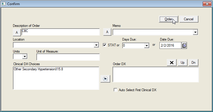
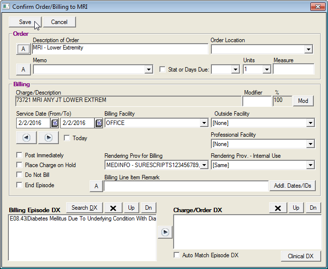
If the tree node has both an order property and billing property, the confirmation window combines both billing and ordering in one step as shown below.
Features available to the end user:
The user is able to override the contents of the “Description of Order” field and “Memo” field by clicking on the buttons marked “A” (Alphabet button) next to each field. This brings up an on-screen keyboard which users can fill in using a pen.
The ordering provider may override the stat or Days Due value. Days due control when the order will be marked as overdue while stat ensures that the order is due immediately and also places it ahead of other orders.
Features the designer can include:
All orders require that a diagnosis code be given to validate the reason for the study (if the order is a test). If the order does not require a diagnosis, specify exclusion of the department from this requirement in the DEPT.TBL file as explained later (see Advanced Orders Configuration in DEPT.TBL).
Order Location is used to indicate a location where the order will be performed (or tracked to completion) and these are values entered in the Order Location table. (Preferences, Order Locations). This is important in cases when multiple individuals are responsible for performing the orders in different locations. Specifying a location allows the ordering provider to indicate who will perform the order. Typically, each nurse station location is assigned an order location.
Advanced Orders Configuration in DEPT.TBL
Below are the contents of the standard DEPT.TBL installed with the Primary Care Decision Tree, which is located in the OUTLINE directory.
The following settings will control if an order for a listed department code will require an order confirmation window.
[Confirm]
LAB=Y
RAD=Y
ULTRA=Y
NUCL=Y
REF=Y
INJ=Y
IV=Y
PATH=Y
CT=Y
MRI=Y
NURSE=Y
PROC=Y
TRANS=Y
SCHED=Y
SCHDP=Y
REFD=Y
SURG=Y
EDU=Y
REFUS=N
If Order Confirmation is specified, departments will not require a diagnosis to be supplied if set to "N" as displayed below:
[Diagnosis]
NURSE=N
LAB=Y
RAD=Y
SCHED=N
VER=N
TRANS=N
EDU=N
INJ=N
IV=N
PATH=Y
PROC=Y
SCHDP=Y
REF=Y
REFD=Y
SURG=Y
ULTRA=Y
CT=Y
MRI=Y
NUCL=Y
REFUS=N
The following settings will determine if tree nodes with both orders and billing properties will be allowed to do billing. When turned off with a “N”, the listed departments will not be billed if both orders and billing properties are defined for the node. This allows standard decision trees to be modified globally for billing without having to modify each tree node property individually when a site does not do billing for certain orders, such as labs. For example, a client with the Standard tree installed does not bill for ultrasounds, but bills for labs. The designer would add an “N” to the ULTRA department.
[Billing]
RAD=Y
ULTRA=N
LAB=Y
NURSE=Y
IV=Y
INJ=Y
PROC=Y
REFD=N
REF=N
NUCL=N
CT=N
MRI=N
REFUS=N
In Workflow Views, the Order View has a filter that allows orders to be listed according to department. This department filter can be set up as a macro so that the actual displayed department can include orders for several departments. This allows regrouping of duties to fit the environment. For example, in a small practice, the Front Desk person is responsible for scheduling, insurance verification, and referral authorization. Thus the Front Desk position can be made to see the department codes “SCHED”, ‘VER” and “REF”, which match the person’s responsibilities.
To make this work in Orders View, two sections need to be completed: [Departments] and [Dept Group]. Note that departments not defined in the sections below cannot be shown in Orders View. For example you will see that “EDU” for patient education is not displayed because it does not require followup.
The following section defines the filters that will appear in Orders View:
[Departments]
NURSE-Nursing Staff Orders=1
LAB-Lab Orders=1
RAD-Radiology Orders=1
SCHED-Scheduling/Referrals=1
VER-Insurance Verification Order=1
TRANS-Transcription Orders=1
*=All
;EDU-Physician Education=1
;INJ-Injection Orders=1
;IV-IV Orders=1
;PATH-Pathology Orders=1
;PROC-Procedures Done Today=1
;SCHDP-Schedule Procedure=1
;REF-Referrals to Specialists=1
;REFD-Referrals for Diagnostic Services Done Elsewhere=1
This section is where the filter is actually specified to include a certain group of departments.
[Dept Group]
NURSE=NURSE,IV,INJ,PATH,PROC,LAB,SCHDP,REFD,
ULTRA,CT,NUCL,REF,SURG
SCHED=SCHED,SCHDP,REF,REFD,SURG
USER=LAB,NURSE,RAD,ULTRA,CT,MRI,NUCL
PATORDERS=NURSE,PATH,PROC,LAB,SCHDP,SCHED,REFD,ULTRA,
CT,NUCL,REF,SURG,MRI,RAD,VER
*=NURSE,LAB,RAD,SCHED,VER,TRANS,INJ,IV,PATH,PROC,SCHDP,REF,
REFD,SURG,ULTRA,CT,MRI,NUCL
The PATORDERS entry is not an actual department but is a custom value, which is used to define the orders that will appear in the Patient Orders window.
Following is a master list of valid department codes. All departments used in Order entry must be defined in this list. Department Code cannot exceed 5 digits.
[Dept Codes For Order Table]
NURSE=1
LAB=1
RAD=1
SCHED=1
VER=1
TRANS=1
EDU=1
INJ=1
IV=1
PATH=1
PROC=1
SCHDP=1
REF=1
REFD=1
SURG=1
ULTRA=1
CT=1
MRI=1
NUCL=1
REFUS=1
One can now auto-execute a URL or launch an EXE from Orders when clicking on the Chart Button. To do this, make an entry in DEPT.TBL as follows:
[Execute]
LAB=http://www.mylab.com/&ACCOUNT/&COMPANY
In the above example, LAB is the dept code and the http includes some global variables which will be translated/interpreted before being executed.
Rx Property
The RX Property causes a tree node click to initiate an Add Medication event to occur.
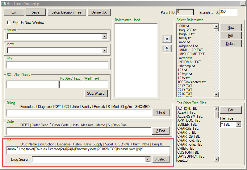
Prescriptions are entered using the following format:
Drug Name|Instruction|Dispense|Refills|Days Supply|Subst OK|Pharm Note|DrugID|Unit of Measure|Use for|Internal Note|Site|Route
All parameters other than for the Drug Name are optional.
An unused parameter is still delimited by a “|” Pipe symbol (it must be included) and spaces at the end of each parameter are ignored.
When using the above RX Property in the Tree, a drug with a complex name and description may not be identified in the drug list as it searches for the prescription (which is Drugname + Strength) through the drug tables under the assumption that the first word is the drug name and subsequent words are strength. Although this is sufficient for Allergy Tracking purposes, misspellings of the drug name(s) past the first word will not be corrected.
To allow for more accurate identification of the drug from the Tree, an optional feature has been added so that the Tree Property using the old format will still work. The new format will allow handling of multiword drug names. This format is:
Drugname^Strength|Instruction|Dispense.
Using the alternative RX Property, the following drug name descriptions will be valid:
Aspirin 81 mg
Aspirin Adult Low Strength^81 mg
The following format would not be valid:
Aspirin Adult Low Strength 81 mg
This change will require changes of RX Properties in the tree for best use. If the tree properties are not changed, the effect will be that the Drug List Search window will pop up so that the user can select the desired drug. Proper identification of the drug on the tree will avoid extra clicks.
- When adding a prescription via a Decision Tree Branch and the medication specified cannot be found in the medication database, the Drug Search screen will be displayed allowing the correct medication and strength to be selected. If the medication specified is found in the medication database, the standard Add Rx screen will be displayed.
- When a medication is selected via a Decision Tree branch, the Drug List search screen will always be displayed and the list of choices presented will be based on the drug and strength specified in that branch. The first Drug ID found that has the same name as the drug specified will automatically be displayed. If the name is incomplete or if there is no match in the Drug Database, the Drug List Search screen will be displayed so the user may pick one of the existing drugs.
- A security right called “Force Search of Drug ID when doing RX from tree” has been added to provide stricter documentation of the actual drug form (i.e. tablet vs. chewable). When enabled, the drug list will always display.
- Drug List Search capability has been modified to allow the drug strength specified. In addition to searching for only a drug name, the user may now enter a specific drug name and strength (i.e. Amoxicillin 250mg) and a smaller list of drugs matching the criteria will be displayed.
The fields are defined as follows:
Drug Name – This drug must match the name of a drug in the Drug List (a standard list of drugs provided by MedInformatix). The full Drug name and strength should be given to take full advantage of this feature and must match exactly with the drug list. Example: Mevacor 20 mg. Clicking on the Find button will take the designer to the Drug List screen where details on the Drug Name and Strength can be determined.
If a drug name is given without the strength, the user is required to click on the Drug List button after an Add Medications window appears. This will allow selection from a list of drugs with the indicated name but different forms.
Instruction/SIG – This is a free form field used to indicate dosage instructions. You can customize the common list of instructions by modifying the file SIG.TBL in the OUTLINE directory. (i.e. 1 PO QID)
Dispense – This field is used to indicate the number of units of medicine to be dispensed. For example, the format of #30 or 30 Tablets is acceptable. The Dispense combo box can also be customized by editing the DISPENSE.TBL file in the OUTLINE directory.
Refills – This is a number that identifies the number of refills allowed.
Days Supply – This field is used to specify how many days the patient is supposed to take the medication.
Subst OK – Allows the designer to have the Generic Substitution Allowed field default to selected or deselected. (Enter Y or N.) If “Y”, this value can be overridden on the confirmation window when creating the prescription.
Note to Pharmacy – Allows the user to enter a note to the pharmacy that can be printed on the prescription.
Drug ID – This will be auto populated when the drug name is selected.
Unit of Measure – This field uses values from “EXEC mi_clrxhistDrugSearchSel” when medication is selected during configuration of the tree link.
Use For – This field indicates how the prescription will be utilized: I = Internal, U = uncoded/OTC, E = Prescibed by Other Provider, S = Samples, A = Administered On-Site
Internal Note – Allows the user to enter a note to be seen by the provider only.
Site – Allows the user to designate the site in free text using the values from CLVALUESETS.
Route – Allows the user to designate the site in free text using the values from CLVALUESETS.
[Configuration]
Add Meds=”&Plname, &Pfname Age: &AGEPEDS Wt (Kg): &!{SELECT DISTINCT Convert(float, WEIGHT)/2.2, SQRT( convert(float,WEIGHT)*(convert(float,HEIGHT) )/3131) FROM CLVITAL WHERE SSNO='&MRNO' AND COMPANY='&COMPANY AND VDATE='&DATESQL2K' }&SQLCOL001 BSA: &SQLCOL002&SQLEND”
Customized Rx Program
Customized RX Program – You can now call a custom RX program instead of the standard MedInformatix RX system. This is done via a Custom Change: The following entry in TREE.TBL (TREE Folder) will launch an alternate RX Program:
[Configuration]
Custom RX Program=CUSTOM.EXE &ACCOUNT
Note: CUSTOM.EXE would be replaced with the name of the custom RX program.
Prescription/Add Medications Event
When the node is clicked in the decision tree, the Add Medications screen will open with the prescription information automatically populated.
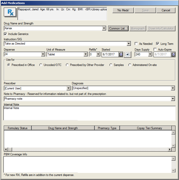
When the user selects the node with the Rx property, the Add Medications screen opens with the information displayed. The fields are defined as follows:
The Drug Formulary Options – The Drug List; Ingredient List; Formulary Check; and Common List are used to select drugs and strength already in pre-assigned categories and based on pre-entered drug formulary codes. Thus patients who are limited to certain formularies can be given only drugs on the formulary list (unless overridden by the physician).
The Calculator button brings up an on-screen calculator. To aid in the calculations, certain values have been pre-computed such as Body Surface Area and Kilogram Weight, based on today’s vital signs.
Drug Name and strength – If specific medication is selected, the full Drug name will populate. Example: Mevacor 20 mg.
If no drug is listed or a drug name is given without the strength, the user is required to click on the Drug List button after an Add Medications window appears. This will allow selection from a list of drugs with the indicated name but different forms.
A user may change the Drug Name and Strength directly using the “A” (alphabet keyboard) button only if the drug is marked as “Prescribed by Other Provider/OTC” (meaning it is not considered to be a prescription.)
Instruction/SIG – This is a free form field used to indicate dosage instructions. The field can be completed by using the “A” (alphabet keyboard) or using the combo box to pick an entry.
Dispense – User has the option of using the dropdown arrow to select or directly enter the number of units of the medicine that should be dispensed. (i.e. 30)
Unit of Measure – Shows the values from “EXEC mi_clrxhistDrugSearchSel”
Refills – This is a number that indicates the number of refills allowed.
Started – Allows the date of the prescription to be added, which defaults to today’s date.
Days Supply – This field is used to specify how many days the patient is supposed to take the medication.
Auto Expire – Allows the physician to specify a follow-up date (number of days), after which it is expected that the drug prescription will have been used up.
Prescribed In/By Other – Allows the user to record medications used by the patient other than those prescribed in the office. All medications added are identified as “Prescribed in Office” (and thus given a flag of Internal) or “Prescribed by Other Provider/OTC” (which is given a flag of external).
Prescriber – Allows the user to select the prescriber for that prescription. The field auto populates with the current user, but the dropdown list allows the user to select another prescriber authorized to prescribe from a particular site.
Diagnosis – Allows the user to record a diagnosis with the prescription. The field populates with the primary diagnosis, however the dropdown arrow allows the user to select from all diagnosis recorded for the patient.
Note to Pharmacy – Allows the user to enter a note to the pharmacy that can be printed on the prescription.
Internal Note -- Allows the user to enter a note that will not be sent to the pharmacy
Formulary Alternatives – If formulary check is enabled, each time a drug search is performed, the drugs will be checked against the formulary of the patient’s health plan and choices will be listed in this field.
Changing the Clipboard Side Window Text
The right side of the Decision Tree has a clipboard area which functions as a permanent View Property for the tree. It usually stays fixed to each Tree INI file. It is defined on the Set Item Property window under the Setup Decision Tree button in the field labeled Side Window Text. A text file name found in OUTLINE directory is placed here.
Using the View Property, Setup Decision Tree, one can cause the contents of the Side Window Text to change by specifying a “#” plus the filename. Instead of displaying the usual View window, the desired text will be displayed on the Side Window text.
Example: #VWSIDE.TXT
Boilerplate Property
When a tree node is clicked, the system can automatically remember snippets of text called Boilerplates that are associated with the particular tree node. At the end of the patient encounter, the physician clicks on the Document button and all the remembered text is sorted and organized according to a predefined sequence. The text also has embedded SQL statements in them to pull the current data from the medical database. After final formatting is done, the completed document is presented.
Boilerplates
The text that appears with each tree node can be made up of one or more boilerplate files. Usually each boilerplate file contains text particular to one context only. (i.e. Problem List) This helps with consistency in being able to reuse or copy the boilerplates into other tree nodes. If several snippets of context are contained in one large boilerplate file, the boilerplate becomes very complex and is typically not reusable.
One example is medical documentation where separate boilerplates are often made for each section of the medical record. The History section may be designed to include the Chief Complaint, HPI, ROS, Family History, Social History, Past History, but are each given separate boilerplate files (one or more).
Boilerplates must be text files with a TXT extension and must contain ANSI text. It must be readable using NOTEPAD.
Document in Progress
As each Tree node is clicked, the system determines if boilerplates are attached to that node. If so, the system records the names of the boilerplates in an area set aside for keeping documents in progress that will eventually be compiled into a finalized document. Boilerplate properties are not necessarily attached to each node. They are instead organized so that entry in a specific area of documentation brings up the whole paragraph related to that area. In some cases, boilerplates can trigger at a later point in the tree flow where the user is certain to pass through.
Creating the Final Document
The final document is compiled when the Document button on the chart menu is clicked.
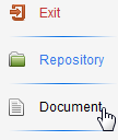
A document similar to that shown below will display.
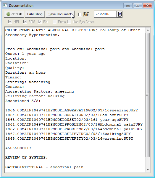
The text included in the document is generated by first determining the list of boilerplate names that have been selected due to a tree node click. These boilerplates are then sorted based on a Sort Level value that has been assigned to each boilerplate. This ensures that text will always appear in the same sequence regardless of order of selection. Also, duplicates in the boilerplate names are removed. The text associated with each boilerplate is then read in the exact sequence as the boilerplate names, which makes up the document.
The document will have embedded SQL queries that can pull results from the database. Thus, although the text boilerplates are fixed, the data that is included in the final document will reflect the most recent data available.
A feature called the Document Interpreter automatically reads each text file and executes all embedded SQL statements and formats the results. The Document Interpreter, which is explained in detail later in this manual, is a special programming language that is used to create dynamic documents; documents with data based on a database, rather than static text. It has the capability of conditional formatting as well so that complex queries to the database can be presented as normal appearing paragraphs. Thus, a complete understanding of Boilerplate Properties can only occur after the capabilities of the Document Interpreter are known.
One can also change the date of the document (which defaults to today’s date) using the Date field options presented on the screen. The date selected is stored as the service date and will be used for sorting of the document in the repository.
How Boilerplates are Created
Boilerplates are created from the Set Item Property Window by clicking on the New button in the Select Boilerplate section. You may also view an existing boilerplate by highlighting the name of the boilerplate on the list box and clicking on Edit.
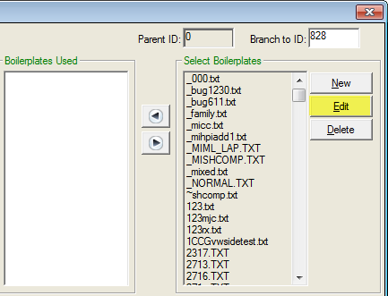
Either of these steps opens the Boilerplate Editor window.
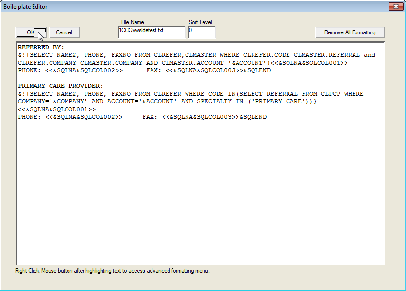
The text in the above boilerplate does not appear or “read” as normal text because it includes embedded SQL queries and formatting instructions. Note that there is a Sort Level assigned to this boilerplate (Sort Level field), which indicates the order in which this text will appear in a final document.
Boilerplate Naming Conventions
It is very important to assign a fixed naming convention to new boilerplates. Without a strictly followed naming convention, it will be very difficult to maintain boilerplates or know what is contained in a boilerplate. There can be hundreds of boilerplates in a typical medical specialty specific Decision Tree. The following shows the two-letter prefix used to name boilerplates.
PREFIX |
CATEGORY |
CC |
Chief Complaints |
HP |
History of Present Illness |
RS |
Review of Systems |
PH |
Past Medical History |
SH |
Social History |
FH |
Family History |
PE |
Physical Examination |
VW |
View Text – Used by View Text Property |
DX |
Assessment/Diagnosis |
LAB |
Laboratory/Pathology/X-Ray |
PR |
Procedure/Surgery |
PL |
Plan |
Boilerplate Sort Level Conventions
Boilerplates are usually used to create medical documents. These documents follow a strict format and data order. Sort Levels are numbers assigned to each boilerplate and are used to determine the order in which the text will appear in the final document. Given that each boilerplate belongs to a certain section of document, each will have a specific position whenever they are used. To make this consistent, a pre-made convention for numbering boilerplates has already been included and is shown below.
PREFIX |
LEVEL RANGE |
DESCRIPTION OF LEVEL |
VW |
0 |
View Text - These boilerplates are not actually boilerplates. The prefix is reserved for View Property and is not used to create documents. Therefore, a level value does not apply. |
CC |
1000-1999 |
Chief Complaint Boilerplates |
HP |
2000-2999 |
History of Present Illness Boilerplates |
RS |
3000-3999 |
Review of Systems Boilerplates |
PH |
4000-4999 |
Past History Boilerplates |
FH |
5000-5999 |
Family History Boilerplates |
SH |
6000-6999 |
Social History Boilerplates |
PE |
7000-7499 |
Physical Examination Boilerplates |
LAB |
7500-7999 |
Lab and Radiology Results Boilerplates |
PL |
8000 |
Diagnosis Boilerplates |
PL |
9000 |
Diagnostic Tests Ordered Boilerplates |
PL |
10000 |
Prescriptions Given Boilerplates |
PL |
10100 |
Education/Handouts Boilerplates |
PL |
10200 |
Free Form Plan of Action Boilerplate |
PL |
10300 |
Procedures Ordered Boilerplates |
PL |
10400 |
Referrals Ordered Boilerplates |
PL |
10500 |
Injections Given Boilerplates |
PL |
14000 |
Scheduler/Return Visits Boilerplates |
Decision Tree General Setup
Several parameters can be configured for each Tree INI file (Tree structure file).
If no node is selected, clicking on the Property button will open the Decision Tree Setup window displayed below.
If a node is selected, clicking on the Property button displays the Set Item Property window for the selection. Clicking on the Decision Tree Setup button will then open the Decision Tree Setup window.
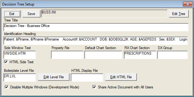
The Decision Tree Setup window contains setup information about the specific tree structure. The name of the INI file is stated at the top, which in this case is labeled as DREX.INI in the OUTLINE directory. If you are an advanced user, you can actually examine the contents of the Tree structure file directly using the Edit Tree button.
Tree Title: You can specify a title of your choice in the Tree Title field, which will appear on the Window caption bar.
Identification Heading: Information about the patient can be placed in the Identification Heading field. Notice that in the above example, text appears with special symbols. These are recognized as special variables by the Document Interpreter and are converted to data. This is discussed in more detail in the Document Interpreter section.
Side Window Text: This field is used to specify the file name of the text file that will be used to populate data in the clipboard window.
Property File: Under normal circumstances, the tree structure data and the tree node properties are kept in one Tree INI file. However, when the trees become too large, an option exists to place the properties into a separate file (which by convention is the same first part of the name plus the extension “.PRO”). This will reduce the possibility of exceeding the 64K limit on Tree INI files.
Default Chart Section: You can specify which chart section will first be displayed when you enter the Document Repository. This can be specified for each Decision Tree under the field Default Chart Section.
RX Chart Section: The Decision Tree is capable of creating prescription documents. You must specify here which Chart section will be used for storage of prescription documents. If you are using the standard chart sections provided by MedInformatix, this value is “74”.
DX Group: This field allows a tree designer to assign a value that will be used to filter out the common list of ICD9 codes in the ICD9 Search window. This will cause the system to select items for display in the Common List (new Database Version) only if they contain this DX Group. Thus, one can vary the ICD9 codes displayed by tree since each tree may have its own DX Group Code.
Boilerplate Level File: Displays the current boilerplate level file. This option allows the user to specify an alternate level file name.
Edit HTML File: This program feature opens the HTML version of the selected decision tree file in a text editor.
Auto Create HTML File: When this option is selected an HTML version of the selected decision tree file will automatically be created and saved when the Save button is selected. The decision tree will also be displayed in HTML format when this option is selected.
Disable Multiple Windows (Development Mode): This option is used to prevent the system from displaying a new “pop up” window when tree nodes are given the property to “Pop-Up New Window”. This is important because you cannot change tree nodes if a pop-up hierarchical window is active. Clicking on this box temporarily disables this feature until you re-login or change this setting again and hit the Reset button.
Share Active Document with All Users: This option is used when you wish to have multiple users contribute to the creation of one document. When a physician has split tasks with other ancillary staff, when another staff member clicks on the Decision Tree, this option will allow boilerplates to be remembered for all users. If this option is not selected, it is assumed that each user is responsible for his or her own document only. Thus, only the user’s own selections on tree nodes will cause boilerplates to be included in a document.
Advanced Decision Tree Configuration
The following settings are now allowed in the Decision Tree Configuration file TREE.TBL in the OUTLINE directory:
[Configuration]
View Saved Document=0
When set to “0” documents saved in the repository using the Document Button will not be redisplayed immediately after saving. The default is “1” which displays the Document Repository so that the provider can sign with ink,
Auto Sign Saved Document=0
This option is used in conjunction with the option for viewing saved documents. Normally, the only reason the document is viewed in the Document Repository is to be able to sign it. When this option is set to “1”, an electronic signature window will immediately pop up after saving. This will save the extra steps of going to the repository and signing the document.
By default, the value is set to “0” which means that no automatic electronic signature window will appear.
Delayed Interpretation=0
This setting will turn off the “Delayed Transcription” capability described in a separate chapter. This will cause all the SQL Scripts for Delayed transcription to be interpreted and thus not appear in the Documentation window. It is useful to use this setting if there is no intent to ever use the delayed transcription feature.
Chief Complaint from Appt=1
When this entry is made, the system will default the reason for visit in the #CHIEF (Chief Complaints window) to the appointment reason of the patient. This is a setting that could be important in certain specialties where the reason for visit is usually clearly indicated by the appointment description.
In addition to the changes to TREE.TBL, you may also make the following entry in each Decision Tree INI file.
Auto Exit Tree On Save=0
When saving a document, the default behavior is that upon exiting from the repository, you automatically exit the tree as well. If the saving of the document is not the last step with the patient, this behavior can now be overridden so that you return to the tree. The TREE.TBL setting will eliminate the auto exit.
[General]
Save Chart Section=1
This setting allows you to specify the default chart section when saving from the Document button. If the decision tree is fixed, this setting can eliminate the chart section confirmation window, which appears each time a document is saved using the Document Button. In order to have more flexibility, this change was placed on the Tree INI file. Thus, if you are in the Procedures Tree, you may save the documents to a different section than if you were in the Evaluation and Management Tree.
The default value is to not have this entry defined. This will cause the system to display the choices of chart sections as before.